
Morph 4K
![]()
Introduction

PixelFX Morph 4K is an advanced, modular scaling solution based around a powerful FPGA architecture. The device has been designed to bring powerful, flexible 4K scaling tailored for video game material to users at an affordable cost.
By being modular in design, the unit can be customized to a users exact needs and setup, therefore saving the end user considerable expense. The base unit has one HDMI input. Expansion modules allow the device to accept various analog signals too.
Features
- Up to 4K60 resolution polyphase upscaling
- 4:4:4 end to end color support
- HDR, Variable Refresh Rate, Black Frame Insertion
- Ultra low lag
- Motion adaptive deinterlacing
- Scanlines, adaptive scanlines and slotmask emulation
- Image Smoothing (including XBR)
- USB socket (for future use)
- WiFi updates
- WebUI system control
- Control by IR remote, web interface or CEC
- MicroSD card slot for updates and user files (FAT32 or exFAT formatted)
- Expansion card support, modular design
Board versions and availability
Morph 4K is sold as a base unit (22cm L x 9.2cm W x 3.8cm D) with HDMI input. In the future, optional add-on cards will expand its range of inputs and outputs.
Preassembled base units are sold worldwide by:
Other resellers are expected to be added post launch.
More information & discussion
External Inputs, Outputs, and Ports
Front Panel Functions

All Morph 4K's are constructed with a front physical power switch (off/on), an LED indicator, IR sensor, microSD port, and 6 navigation buttons.
Physical Switch, LED Indicator, and IR Sensor
Power Switch - Physical power switch. Push to the right to turn the unit on and to the left to turn it off.
LED Indicator - Light emitting diode that glows or flashes in various colors to communicate various statuses to the user. The front LED will glow light blue when the Morph is powered on and working normally.
LED Colors and Meanings:
- Blue for initial boot, then goes to color in Morph Setting (Blue by default, yet can be customized to match OSD Colors)
- White for standby mode via the remote's power button
- Enters color sequence during SD card flashing (Red blinking x2, Green blinking x5, Yellow blinking continuously, turns White when finished)
- Red blinking x2 continuously for WiFi access point as part of Rescue System via WiFi
G.E.M. Specific:
- Breathing = HPD (hot plug detection) waiting for connection or installation issue on the 5v rail
- Solid = connection established
- Blinking = error -> check installation; check if the correct jumpers are closed on the GEM -> try flashing the FW again and reformat FS while doing so
IR Sensor - Detects button presses by the included IR remote and can also be used to customize additional remotes in the WebUI.
MicroSD Port
A microSD card must be inserted (printed side up) at the front of the unit, next to the front panel buttons. This is used to manage presets, flash firmware, write a debug log, and store other related files.
- Must be in FAT32 or exFAT format
- Storage amount can be as low as 4GB (custom presets may demand more storage so consider between 8GB and 32GB to be on the safe side)
- Formatting tools:
- SD Card Formatter (Windows, MacOS, or Linux x86_64)
- 4GB-32GB will format to FAT32
- Greater than 32GB will format to exFAT
- FAT32 Format (Windows x86 or x64)
- Any size will format to FAT32
- Might require SD Card Formatter first to fix any issues
- SD Card Formatter (Windows, MacOS, or Linux x86_64)
- Recommended Brands:
- SanDisk
- Samsung
- Kingston
- Toshiba
Note: Purchase from retailers such as WesternDigital.com, Samsung.com, Kingston.com, Best Buy, Amazon (shipped & sold by), Walmart, Newegg, Micro Center, etc. Avoid SanDisk or Samsung clones sold by a third-party on Amazon, eBay, & AliExpress.
Navigation Buttons
The face buttons on the front of the unit can be used to navigate the Morph 4K's on-screen menu. This is useful in situations where an IR remote is not available. The face buttons also have various context sensitive functions that are documented elsewhere. From left to right the buttons are:
- Circle button - Open on-screen display, enter sub-menus, confirm choice. This is the same as pressing OK on the remote. This button can also be used to perform a manual flash with the microSD or initiate the rescue system.
- Square button - Go back or cancel choice. This is the same as pressing Back on the remote.
- Up button - Navigate upwards in a menu. This is the same as pressing Up on the remote.
- Down button - Navigate upwards in a menu. This is the same as pressing Down on the remote.
- Left button - Decrease a value or navigate left in a menu. This is the same as pressing Left on the remote.
- Right button - Increase a value or navigate right in a menu. This is the same as pressing Right on the remote. This button can also be held for 5 seconds to perform an emergency 1080p reset.
Rear Panel Connections and Power via Base Unit
Morph 4K's base unit includes 4 ports: USB-A, HDMI IN, HDMI out, and USB-C. Even with the ability to expand more rear connections, these 4 ports are included on every unit.
USB-A Port
Morph 4K's base unit has 1x USB port at the rear. This port is currently unused, but will be used in future to control AV switching hardware such as the Infinity Switch (to be released).
HDMI In
The HDMI input port is located directly to the right of the USB port. The port is rated for the HDMI 1.4a standard and will accept up to 1080p video at 60 frames per second with a 4:4:4 color space.
Morph 4K's base unit has 1x HDMI input only. For HDMI equipped consoles, such as Xbox 360, PS3, or consoles with an internal HDMI upgrade (RetroGEM), Morph 4K can accept these devices directly or in combination with an HDMI switch.
For devices that output an analog signal, Morph 4K can be expanded with two module types that accept analog inputs and this allows the HDMI input port availability for dedicated HDMI devices. Alternatively, Morph 4K can accept a second analog to digital scaler (i.e. OSSC) as an "analog bridge" over the HDMI input port.
An orange LED will appear when Morph detects an active HDMI input. The LED turns off when HDMI input is no longer detected.
HDMI Out
The HDMI output port is located between the HDMI input port and USB-C power connector. The port is rated for the HDMI 2.0b standard and is capable of outputting up to 4K video at 60 frames per second in 4:4:4 color space. The port can also passthrough Dolby Digital (DD) & Digital Theater Systems (DTS) audio formats.
USB-C Power Connector
Standard USB-C power connector. Morph's base unit requires a 5V power supply with at least 1.5A of current. With analog expansion cards (bridge/crosspoint), Morph will require a 5V power supply with at least 2.5A of current (3A recommended).
Note that many phone chargers may not provide consistent current and a dedicated power adapter is recommended.
A Raspberry Pi 4, 15W USB-C Power Supply is recommended. (Output voltage: 5.1V, Output current: 3.0A, Output power: 15W)
Rear Panel Connections Expanded via Analog Bridge and Crosspoint

Morph 4K can be expanded with a pcb module that adapts a row of analog connectors. There are two modules, an Analog Bridge and an Analog Crosspoint (to be released). The differences between these two modules is in the manner in which they handle analog ports. The Analog Bridge covers two analog input ports whereas the Analog Crosspoint covers one analog input port and one analog output port. The analog ports come as Connector Cards and are offered in three flavors for each module: SCART & Component, VGA & Component, and VGA & VGA.
Note: Custom made Connector Cards can be generated using a blank card template created by citrus3000psi.
SCART & Component
Port A contains Euro SCART that includes:
- Formats RGBS, RGsB, RGBHV, YPbPr, Composite Video, S-Video*
- Green/Sync Pin support CVBS
- Green/Red Pins support S-Video*
- Sync types accepted: TTL Csync, Attenuated Csync Composite Video Sync, Luma, TTL
- RGBHV capable with vsync on pin 12 via jumper (1.27mm)
Port B contains Component w/ 3.5mm audio that includes:
- Formats RGBS, RGsB, RGB, YPbPr, Composite Video, S-Video
- Green support CVBS (shared with S-Video Port)
- Green/Red Pins support S-Video (shared with S-Video Port)
- 3.5mm audio port accepts S/PDIF (Mini-TOSLINK) or analog audio (Auxillary-to-RCA)
* S-Video only works over the SCART port when luma (Y) is set to green (pin 11) and chroma (C) is set to red (pin 15). This does not follow SCART specification i.e. chroma (C) set to red (Pin 15) and luma (Y) set to sync/composite video (pin 20).
VGA & Component
Port A contains VGA w/ 3.5mm audio that includes:
- Formats RGBHV, RGBs, RGsB, YPbPr, Composite Video, S-Video
- Green/HSYNC Pin support CVBS
- Green/Red Pins support S-Video
- Sync types accepted: TTL Csync, Attenuated Csync, Composite Video Sync, Luma, TTL
- Audio inputs over pins 12 and 15 via jumper (1.27mm)
- 3.5mm audio port accepts analog audio (Auxillary-to-RCA)
Port B contains Component w/ 3.5mm audio that includes:
- Formats RGBS, RGsB, RGB, YPbPr, Composite Video, S-Video
- Green supports CVBS (shared with S-Video Port)
- Green/Red support S-Video (shared with S-Video Port)
- 3.5mm audio port accepts S/PDIF (Mini-TOSLINK) or analog audio (Auxillary-to-RCA)
VGA & VGA
Port A contains VGA w/ 3.5mm audio that includes:
- Formats RGBHV, RGBs, RGsB, YPbPr, Composite Video, S-Video
- Green/HSYNC Pin support CVBS
- Green/Red Pins support S-Video
- Sync types accepted: TTL Csync, Attenuated Csync, Composite Video Sync, Luma, TTL
- Audio inputs accepted over pins 12 and 15 via jumper (1.27mm)
- 3.5mm audio port accepts analog audio (Auxillary-to-RCA)
Port B contains VGA w/ 3.5mm audio that includes:
- Formats RGBHV, RGBs, RGsB, YPbPr, Composite Video, S-Video
- Green pin support CVBS (shared with S-Video and CVBS port)
- Green/Red Pins support S-Video (shared with S-Video and CVBS)
- HSYNC pin supports CVBS
- Sync types accepted: TTL Csync, Attenuated Csync, Composite Video Sync, Luma, TTL
- Audio inputs accepted over pins 12 and 15 via jumper (1.27mm)
- 3.5mm audio port accepts S/PDIF (Mini-TOSLINK) or analog audio (Auxillary-to-RCA)
Note: To use the dedicated composite video input on the dual VGA bridge, you need to choose "Input Port B -> Composite Video over GREEN".

Jumpers
The SCART and VGA ports on the analog connector cards have a bank of 4 jumpers for audio that can be bridged using a 1.27mm jumper (e.g Harwin M50-1900005). The pins on the jumpers should be connected from top to bottom.
Most SCART and VGA adapter audio configurations are reserved for future use. However, if you wish to use the SCART2VGA adapter created by citrus3000psi to convert the VGA port on a connector card into a SCART-to-VGA bridge, be sure to bridge the 5-6 and 7-8 jumpers.
Basic Setup & Usage
Connect your Morph's HDMI output port to an HDMI compatible TV or monitor using an HDMI cable. Remember to use a cable rated for 4K video (at least HDMI 1.4 for 4K 30Hz or HDMI 2.0 for 4K 60Hz) if using a 4K display.
Connect an HDMI source to the HDMI input port of Morph and ensure a suitable power supply is linked to the USB-C connector. Turn on Morph using the physical power switch at the front left of the unit. Verify your TV or monitor is set to the correct input to receive Morph's HDMI output port. You should now see a "No Signal!" message on your TV or monitor. Turn on the HDMI source and within milliseconds, Morph will display it on the TV or monitor.
Remote Control

Morph ships with a basic IR remote control. If desired, a more advanced remote control can be used instead, either via IR or CEC. Remote control through WiFi is also possible once WiFi setup is completed. See Remote Control Setup for more information.
The remote control requires 2 x AAA batteries, these are not included due to postage service restrictions. Insert 2 x AAA batteries into the remote (IR remotes have a low power draw, so rechargeable batteries are perfect) and press the "Menu" button (house icon) to toggle the Morph's menu on or off.
The included remote uses the following buttons as of the current firmware. More functionality may be added in future firmware updates.
- Red Power Button - This button will toggle Morph in and out of standby mode while remaining powered on via the physical switch (as of firmware 3.2.11).
- When entering standby mode, the front LED will turn white. Neither Morph's on-screen menu nor HDMI input source will be displayed on the TV or monitor. If the HDMI input source is still detectable, Morph's rear LED will remain orange. Morph's WebUI is still available, yet features are limited.
- When exiting standby mode, the front LED will briefly turn pink for a few seconds and then change to blue (or if you're on firmware 3.7.6 and set a new default LED choice via the RGB selection in the on-screen menu) to indicate Morph is awake and fully functional. Morph's WebUI is fully available.
- Menu or Back buttons - Two buttons (one with a house and one with a return arrow) acts as a Menu or Back button. This button will toggle Morph's on-screen menu on or off. If you navigate to a submenu option, the button will take you instead to the previous menu. Keep pressing the button to navigate back to the main menu and then again to close the menu.
- Navigation buttons - Use these directional controls to navigate through the main menu, submenus, and to change any operational values.
- OK button - The OK button in the middle of the navigation arrows can be used to enter submenus and confirm changes for an operational value. Remember to press OK if you wish to make a change to any value. If you press the Menu or Back button, the changes will be discarded.
- Shortcut buttons - The colored shortcut buttons at the top of the remote perform various functions depending on the submenu. Throughout this wiki, you will see them referenced as red / green / yellow / blue shortcut buttons.
- Reset to Default button - The button with a left arrow and X in the center will reset a value to default within submenus.
Setting Up Morph
If you have a WiFi connection available, it is recommended to setup the WiFi connection and check for any firmware updates. Morph is a new product and regularly receives new firmware updates. See the WiFi and Updating Firmware sections for more information.
Your next step should be to check that Morph is outputting the most suitable resolution for your TV or monitor. Navigate to "Video" on the Morph's on-screen menu and them to "Output Resolution".
Use the remote to select the desired resolution then press "OK". If your display cannot accept the chosen resolution, Morph will reset to the previous resolution after 30 seconds. If your display is unable to accept a 4K signal from Morph, despite being rated for 4K use, please check that your HDMI cable is rated for 4K.
Usually you would choose the highest resolution that your television can support. Typically for a 4k television, you would choose "4K" as the output resolution. However, if you want to use the Black Frame Insertion feature (Insert data) you would choose "1080p120" instead.
You are now ready to start exploring Morph's functionality. For an overview of what you can do with various sources, proceed to the next section.
Console Connection Basics
Morph can accept and process signals from a huge range of games consoles, computers and even video equipment. The focus of the Morph is for scaling and processing video games although it can also be useful in some instances for processing video material too. Below is an overview of different types of consoles, how they connect to the Morph and how you might wish to process them with the device.
Pre-HDMI Gaming Consoles and Computers
This category encompasses all games consoles before the seventh generation, and some seventh generation machines such as the Nintendo Wii and the original launch Xbox 360. Typically these machines will connect to the Morph in one of three ways.
- With an internal HDMI upgrade (RetroGEM) or an external adapter
- With a second scaler as an analog bridge
- With an expansion module fitted to the Morph 4K's base unit
Using either a good quality HDMI upgrade or adapter or the dedicated analog expansion card on the Morph will yield the best results. However, utilizing a secondary scaler (such as an OSSC) can also produce excellent results.
To connect using a HDMI upgrade, HDMI adapter or secondary scaler, use the adapters "pass-though" or "digitization only" mode if one is available. If no passthrough mode is available, choose the lowest output resolution offered by the adapter/scaler and then use the "Prescale" options under the "Scaler" menu on the Morph to effectively undo any scaling the adapter applies.
For specific considerations for each system, see Compatibility and special configuration
What can the Morph do for Pre-HDMI consoles and computers? These machines were typically designed for older displays (especially sixth generation and earlier systems). Morph 4K can properly scale and process these systems and add CRT effects such as scanlines, to make them look as pleasing as they did on legacy CRT displays. For systems which output interlace video (e.g PS2) Morph 4K has a fast, motion adaptive deinterlacer that is optimised for video game content.
Seventh and Eighth Generation Consoles and Gaming PCs Up to 1080p
Systems such as Nintendo Wii-U, Xbox 360 (later revisions) PS3 and gaming PCs from this era typically output up to 1080p/60 via digital/HDMI connections. The Nintendo Switch would also fall into this category. Systems like PS4 which can output higher resolutions and/or HDR have special considerations and will be discussed in the next section.
What can the Morph do for these systems? These machines were typically designed for more modern displays, however the Morph gives you more control over both 1080p and 720p scaling and can produce better results than the scalers that are built into many displays.
Systems such as the PS3, Xbox 360 and Nintendo Wii-U/Switch, which frequently or primarily target 720p, can be upscaled by the Morph to produce either a significantly sharper or smoother image depending on the users preference.
Emulated titles or pixel art style games titles on these platforms (e.g Virtual Console) can be reprocessed by the Morph to correct bad scaling or to add scanlines or CRT filter effects.
Eighth and Ninth Generation Consoles and Modern Gaming PCs
Modern video games consoles and PCs output higher than 1080p resolution. These resolutions cannot be directly processed by the Morph. If you wish to use these systems with the Morph, without limiting their output capabilities, then you will need some way to split or switch their output so that you can bypass the Morph. Remember that many HDMI splitters or switches are not compatible with variable refresh rate that these systems can use.
Many PC graphics cards offer multiple monitor outputs, so in this case it is easy to connect one monitor output to the Morph and the other directly to the display.
What can the Morph do for these systems? Emulated titles or pixel art style games on these platforms can be reprocessed by the Morph to correct bad scaling or to add scanlines or CRT filter effects.
Using a Second Scaler as an Analog Bridge
The Morph 4K can be placed between your display and an existing scaler to instantly upgrade your setup with 4K scaling capabilities. This is an ideal option for anyone who is already happy with their existing analog switching/scaling solution and just wants a simple, low hassle upgrade path to 4K.
For best results with your existing scaler, set the unit to output in "Passthrough" or "Digitisation Only" mode. This will allow the Morph 4K to handle all of the scaling and will produce the best results. If your existing scaler does not support this, use 480p output mode instead and use the Scaler menu to set a /2 vertical prescale on the Morph. Be aware this may mean that your existing device also deinterlaces 480i/576i content, meaning the Morph cannot use it's own deinterlacer.
Some HDMI switches may not support 240p via HDMI. In this case, you can use 480p mode instead and a 2x vertical prescale.
The following devices have a passthrough mode that can be used with Morph 4K:
- OSSC Classic - Activate passthrough mode by following the instructions here
- OSSC Pro - Use in pure or adaptive line multiplication mode, then configure the same as OSSC Classic
- RetroTINK-2X Classic
- RetroTINK-2X Pro - Set the Mode switch to "Pass".
- RetroTINK-5X Pro - Activate downscaling mode by following the instructions here
Be aware that in passthrough mode, clock and phase adjustments will work on the OSSC Classic/OSSC Pro, but optimal presets (256x240, 320x240 etc) require firmware 1.10 (OSSC Classic) or greater.
The following devices do not have a passthrough mode and require prescale conditions to use with Morph 4K:
- RetroTINK-2X SCART - Use 2x vertical prescale
- XRGB-3 - Use B1 mode for minimal lag and 2x vertical prescale
- XRGB Mini Framemeister - Either use 480p output (and 2x vertical prescale) or 720p output (and 3x vertical prescale) depending on preference
Note: When using these devices, if you do not set the prescale, scanlines will not be drawn correctly. See Scaler menu for more information.
Advantages
- Cost - By making the most of your current investment, Morph 4K gives you the lowest possible cost for 4K retro gaming scaling.
- Ease of installation - Few changes should be required to your current setup to integrate Morph 4K. Any existing analog switching hardware can be reused.
Disadvantages
- Added lag - Frame buffer based scalers may introduce lag, this lag will be added to your video chain. Line multipliers generally do not add lag so this disadvantage would not apply to those devices.
- Inherent flaws of some scalers cannot be mitigated - For instance the XRGB Mini Framemeister is known to add noise to some signals, this will still apply when using it with the Morph 4K, of course.
- Resolution changes will still incur a delay - Scalers like the XRGB Mini Framemeister has a very long delay between switching between 480i and 240p content, this will still apply when using the unit with the Morph. Line multipliers like the OSSC and RetroTINK-2X Pro work much better because the Morph will actively keep the connection with your display while it waits for the line multiplier to resync. However, the dedicated analog bridge will still perform slightly better in this regard.
- Remote control - Morph 4K cannot remotely control your existing scaler, for example to select a different input. Using an alternative remote control with custom programmed IR commands could get around this limitation.
On-Screen Display (OSD) Main Menu and Submenus

Morph 4K offers an on-screen display (OSD) navigation that allows you to change various operational values before or during gameplay. From the main menu, the following choices are available:
Presets
The Presets menu is found at the top of the main menu. Presets act as profiles for Morph 4K. This menu can be used to create profiles, manually load profiles, automatically load profiles, and stay up-to-date with a network archive of community made profiles.
By default, you can add mask and color profiles in the .ini or .txt file extension to Morph from your PC by manually placing them on the microSD card in the presets subfolder visible in the file explorer or through the SD Card / Presets manager in the WebUI by placing them in the /sdcard/presets directory.
You can also download the latest preset archive of community made profiles directly to Morph with a WiFi connection. This archive will automatically store on the microSD card.
Presets can also automatically load based on detection of CEC, Game ID, Mode, and SPD.* All of these appear under the /sdcard/presets/Auto folder in the following structure:
- /By_CEC* - For consoles or devices that communicate over CEC protocol (such as Nintendo Switch's Match TV Power State option)
- /By_Gameid* - For any consoles or devices that can provide Game ID details
- /By_Mode* - For standard HDMI or analog device detection
- /By_SPD* - For Source Product Description (SPD) InfoFrame format detected over HDMI (such as DV1 or FXD)
Presets Menu Navigation

The following operations are handled under the Presets menu:
| Operation | Details |
|---|---|
| Browse presets | Opens the preset file browser under /sdcard/presets on the microSD card that allows you select a preset file and navigate subfolders. Click OK to confirm which file to use, and use Back to navigate out of subfolders and exit. |
| Save as auto preset* Delete auto preset* |
Allows you to save the loaded preset file as an auto preset option based on the input detection (HDMI or analog) or delete the selection. The preset file is rendered as a copy under the /sdcard/presets/Auto/By_Mode subfolder. Use OK to select which option to save as or delete, then click Back when finished. Options are as follows: - GameID for input (width and height) / for input (no width) / (no width / height) - Analog for input (width and height) / for input (no width) / (no width / height) - Mode for input (width and height) / for input (no width) / (no width / height) - Default |
| Create new preset | Creates a new preset based on current settings in the /sdcard/presets/New folder. Click OK to create, then click Back to return. |
| Save to preset | Allows you to save over the Loaded preset. Click OK to override or click Back to cancel. |
| Reload auto preset* | Reloads the auto preset under the current preset context in the /sdcard/presets/Auto folder as the loaded preset. Click OK to reload, then click Back to return. |
| Restore previous settings | Restores the last loaded settings. Click OK to restore, then click Back to return. |
| Restore default settings | Removes all scanline, mask, and custom scaling settings. Click OK to revert to default, then click Back to return. |
| Install/update from presets archive | Downloads the latest presets from an archive that is available over WiFi and loads it under /sdcard/presets on the microSD card. Click OK to run the update, then click Back when finished. |
* Requires Preset auto-load setting turned on in Morph Settings and CEC setting must be turned on in OSD.
Input
The Input menu is for choosing your input source. On Morph's base unit, the HDMI input is the only input source available and this has a few input settings available. When an Analog Bridge and Connector Card are installed, the input sources appear as follows.
- Port A
- Port B**
- HDMI

Contained within Port A and B is a submenu to choose the analog input type.
- Composite Video over GREEN (CVBS green)
- Composite Video over HSYNC (CVBS hysnc)
- S-Video
- Component (YPbPr) (YCbCr)
- RGB(HV/S) (TTL sync levels) (RGB TTL)
- RGB(S) (75 ohm sync levels) (RGB 75)
- RGsB (sync on green) (RGsB)
After the correct analog input type is chosen, then Morph will display the active analog source along with various input settings.
** Since Port B accepts multiple input connections, be sure to power on a single analog input at any given time on Port B. This is to avoid crossing frequencies when multiple inputs are active over a shared port.
Input Settings Navigation
HDMI Input Settings
| Setting | Details |
|---|---|
| Input CS | For setting the input color space of the HDMI source. By default, this is set to Auto, yet in some cases may need to be changed. The setting appears greyed out when the input signal isn't HDMI. For example, if the input signal is DV1, then Input CS has no effect because DVI is always RGB full range by definition. The following options are available: Auto, Auto (no ITC), RGB AVI Limited2F, RGB Limited, RGB Full, YCbCr 601 Limited, YCbCr 709 Limited, xvYCC 601, xvYCC 709, YCbCr 601 Full, or YCbCr 709 Full. |
| 422 Interp. | For HDMI sources with 4:2:2 chroma subsampling, turn this option on. Otherwise, leave it off. |
| Metadata adjust - DE left + right - DE top + bottom - Horiz. Prescale - Vert. Prescale |
For adjusting the horizontal and vertical metadata and prescale of the HDMI source for certain HDMI sources that may require custom adjustments. Values can be incremented by 1 using the left or right navigation or by 10 (coarse) using the yellow or blue shortcut buttons on the remote. |
| DV1/FXD | For detecting DV1 or FXD input from HDMI sources that support it, turn this option on. If neither DV1 or FXD will be used on the HDMI input source, then turn it off. |
| EDID | For setting the Extended Display Identification Data (EDID) detection of the HDMI input source. The default option is default.bin and for most sources, this is the best option to use. Yet in certain cases, another EDID may be required. Options are as follows: h-dac.bin (for Analogue consoles like Mega Sg, Super Nt, and Analogue Pocket Dock), a-dac-ntsc.bin, a-dac-pal.bin, or 2ch-pcm-only.bin. Advanced users can also use this option to select a custom EDID file. |
Port A or B Input Settings - Main

Note: All values appear grey by default. When you change a value, it will appear yellow before clicking OK to save. Once a value is changed and saved, it will appear white.
| Setting | Details |
|---|---|
| Horiz. Samples | For adjusting horizontal samples (i.e. the number of data samples the ADC captures across the entire line referenced by the horizontal sync signal). The value can be incremented by 1 using the left or right navigation or by 10 (coarse) using the yellow or blue shortcut buttons on the remote. Also useful for the Auto Crop feature that will crop the image to match the input resolution. Auto Crop is ran using the red shortcut button on the remote. Remains fixed on CVBS green, CVBS hsync, and S-Video input types. Toggle revert allows you to reset all values back to default using the green shortcut button on the remote. |
| Horiz. Phase | For adjusting horizontal phase degrees. The value can be incremented by 1 using the left or right navigation or by 10 (coarse) using the yellow or blue shortcut buttons on the remote. Remains fixed on CVBS green, CVBS hsync, and S-Video input types. |
| DE - left + width - top + height |
For adjusting the Data Enable (DE) signal's horizontal and vertical parameters for the displayed image. Values can be incremented by 1 using the left or right navigation or by 10 (coarse) using the yellow or blue shortcut buttons on the remote. Under DE width, the Auto Sample feature adjusts Horiz. Samples to get a full width image readback for the given DE width. Auto Sample is ran using the green shortcut button on the remote. |
| Horiz. Prescale | For adjusting the horizontal pixels' prescale factor starting from /1 all the way to /31. |
| Low pass filter | For adjusting the low pass filter (LPF) that limits the anti-aliasing frequencies of the analog signal prior to analog-to-digital conversion (ADC). By default, this is set to Auto. If the input console or device already incorporates a built-in LPF (HD Retrovision Genesis/SNES YPbPr cables, etc), then consider using the Bypass option. Options are as follows: Auto, 9 Mhz, 16 Mhz, 35 Mhz, and Bypass. |
| Audio select | For selecting an alternative audio source beyond the default. Options are as follows: Default, Port A, Port B, or Port B S/PDIF. |
Port A or B Input Settings - Color Submenu (applies to YCbCr / RGB TTL / RGB 75 / RGsB)

Note: All values appear grey by default. When you change a value, it will appear yellow before clicking OK to save. Once a value is changed and saved, it will appear white.
| Setting | Details |
|---|---|
| Gain - Pre-ADC - Red + Green + Blue |
For adjusting the brightness intensity of the analog signal prior to analog-to-digital conversion (ADC) along with the RGB channels post-conversion. Values can be be incremented by 1 using the left or right navigation or by 10 (coarse) using the yellow or blue shortcut buttons on the remote. Also useful for the Auto Gain feature that will adjust the RGB channels automatically. Auto Gain is ran using the red shortcut button on the remote. |
| Offset - Red + Green + Blue |
For adjusting black levels for the RGB channels of the analog signal post-conversion. Values can be incremented by 1 using the left or right navigation or by 10 (coarse) using the yellow or blue shortcut buttons on the remote. |
| ALC V-Filt-Coeff | For adjusting the adaptive loop coefficient (ALC) vertical filter when encountering uneven brightness for certain analog sources. By default, this is set to 1/512, yet can be adjusted to: 1, 1/2, 1/4, 1/8, 1/16, 1/32, 1/64, 1/128, 1/256, or 1/1024. |
| SOG LPF - Threshold |
For adjusting sync on green low pass filter (SOG LPF) and threshold millivolts (mV). By default, SOG LPF is set to 10 MHz, yet can be adjusted to 2.5 MHz, 33 MHz, or Bypass. |
| SS Threshold | For adjusting the sync slicer (SS) threshold to separate csync from SOG. By default, the SS threshold is set to 68. The value can be incremented by 1 using the left or right navigation or by 10 (coarse) using the yellow or blue shortcut buttons on the remote. |
| HPLL - Pre-Coast - Post-Coast |
For adjusting the horizontal phase-locked loop (PLL) in special circumstances when the incoming HSYNC signal is missing or disrupted. This is done with a coasting technique in which the PLL disregards the missing/disrupted HSYNC during the VSYNC pulse interval and instead generates anchored HSYNC pulses as a stopgap approach. Pre-Coast is the period before a VSYNC pulse starts and Post-Coast is the period after the VSYNC pulse ends. By default, Pre-Coast is set to 1 and Post-Coast is set to 0. Both values can be set as high as 255. The value can be incremented by 1 using the left or right navigation or by 10 (coarse) using the yellow or blue shortcut buttons on the remote. |
| Line Length Tol. | For adjusting the line length tolerance's margin sensitivity in order to maintain HSYNC input stability. By default, Line Length Tol. is set to 6, yet can be set as high as 127. The value can be incremented by 1 using the left or right navigation or by 10 (coarse) using the yellow or blue shortcut buttons on the remote. |
| Clamp adjust | For adjusting the ALC clamp start position when encountering uneven brightness for certain analog sources. By default, clamp adjust is set to 0 and can be incremented by 1 using the left or right navigation on the remote. |
Video
The Video menu is comprised of submenus that allow you to change various settings that affect the Morph's scaling and color capabilities. The submenus are as follows:

- Scaler
- Shift / Crop
- Deinterlacer
- Smoothing
- Retro FX
- Color Correction
- Output Resolution
- Advanced Video
Scaler
The scaler menu contains options that directly affect the prescale of the image. This allows Morph to correct or discard any existing scaling that might have been applied to the image and then apply its own scaling. For example, if you feed the Morph 4K a pre-scaled 240p image from a device such as a RetroTINK SCART, that image is already scaled to 480p by the RetroTINK. To un-do this scaling, set the vertical prescaler to /2. The Morph 4K will then apply its pre-scaling settings and scanlines will be spaced in the same interval as on a classic CRT television.
For more information, See this video for a demonstration of using a /3 prescale with a Framemeister set to 720p output.
| Setting | Details |
|---|---|
| Zoom | For zooming the image to the required size. By default, this adjusts based on the Aspect Ratio set to Auto, yet you can adjust the increment gradually by 0.004 using the yellow or blue shortcut buttons or by 0.250 (coarse) using the left or right navigation on the remote. |
| Aspect Ratio | For adjusting the proportional relationship between an image's width and height via the display aspect ratio (DAR) and pixel aspect ratio (PAR). By default, this is set to Auto. Many retro gaming consoles use a 4:3 aspect ratio, while most modern consoles and devices use 16:9 aspect ratio. |
| Horiz. Interpolation | For adjusting the sharpness of the horizontal scale. Leaving this set to off applies a nearest neighbor interpolation. Additional options available that are forms of bilinear: softer, soft, sharp, sharper, or sharper (alt). |
| Vert. Interpolation | For adjusting the sharpness of the vertical scale. Leaving this set to off applies a nearest neighbor interpolation. Additional options available that are forms of bilinear: softer, soft, sharp, sharper, or sharper (alt). |
| Horiz. Prescale | For reducing the horizontal prescale factor starting from /1 all the way to /32. Can be used to correct bad scaling applied by the connected system. Known as "Input Decimation" on some other scalers. By default, this is set to Auto. |
| Vert. Prescale | For reducing the vertical prescale factor starting from /1 all the way to /32. This is typically used with pre-scaled content or pixel art video games to create a more accurate scanline presentation. By default, this is set to Auto. |
Shift / Crop
Use these controls to shift or crop parts of the image. The crop controls are useful for removing decorative borders from some 4:3 content that has been pillar-boxed to fill a 16:9 image, for example. All values can be incremented by 1 using the left or right navigation or by 10 (coarse) using the yellow or blue shortcut buttons on the remote.
| Setting | Details |
|---|---|
| Input Horiz. Shift | For adjusting the HDMI input's horizontal shift. By default, this is set to 0. |
| Input Vert. Shift | For adjusting the HDMI input's vertical shift. By default, this is set to 0. |
| Outp. Horiz. Shift | For adjusting the HDMI output's horizontal shift. By default, this is set to 0. |
| Outp. Vert. Shift | For adjusting the HDMI output's vertical shift. By default, this is set to 0. |
| Crop - Left + Right - Top + Bottom |
For cropping the horizontal and vertical regions of the image. By default, crop is set to Off and all settings are set to 0. |
Deinterlacer
Deinterlacing is the process of converting interlaced video to progressive video. Modern fixed resolution displays cannot display interlace video directly, and this content must be deinterlaced first, either by the deinterlacer built into the display or an external device, such as the Morph 4K.

| Setting | Details |
|---|---|
| Field Order | Refers to the order in which each pair of video fields is processed. Some systems may present interlace content as "Upper" or "Field 2 drawn first". Change this setting to Inverted if you know your target system does this, otherwise leave it set to the default choice, Normal. |
| Method | Choose which method of deinterlacing to use. By default, this is set to Motion Adaptive. All deinterlacing options are as follows: - Bob: Also known as line doubling, takes the lines of each interlaced field (consisting of only even or odd lines) and doubles them, filling the entire frame - Blend: Creates frames by by averaging lines from the two most recent, can produce ghosting effects - Weave: interleaves consecutive fields together into a single frame, can cause combing artefacts - Motion Adaptive: Uses an algorithm to determine the best deinterlacing solution for each part of the image - Simulate CRT: Uses Bob deinterlacing but also more closely simulates how a CRT displays interlace content by alternating the scanlines |
| Sensitivity | Change the sensitivity of the motion detection algorithm for the deinterlacer in order to fine tune it for your source material. Lower values may result in combing artefacts on object edges. |
| Interpolator | Selects how pixels detected as having motion are processed. Only available when the deinterlacer is in motion adaptive mode. - Upper field or Lower field: use bob deinterlacing offset either up or down - Average: linearly interpolates the bob output to make the offset less noticeable |
| Detector | Configure how the motion detector works. Only available when the deinterlacer is in motion adaptive mode. - Zero-lag: Detects motion based on past video fields only - Symmetric: Buffers 1 field additional field to allow for more accurate motion detection at the cost of slightly more input lag |
| Noise threshold | This setting prevents small changes in the image (which could be attributed to picture noise) from influencing the amount of measured motion in the image. Increase this value for noisy sources, decrease for clean sources such as HDMI direct. It can be incremented by 1 using the left or right navigation or by 10 (coarse) using the yellow or blue shortcut buttons on the remote. |
Smoothing
Use the options in this menu to apply an additional smoothing algorithm to the image beyond the softness/sharpness interpolation in the Scaler submenu. Use of smoothing filters is usually a matter of personal taste. You may prefer to use them for all content, exclusively for older 3D content, or not to use them at all. The effects are comparable to the smoothing done by devices such as the Marseille mCable. However, Morph 4K gives you significantly more control over the final image. There are currently two algorithms available:
| Algorithm | Details |
|---|---|
| XBR | Scale by rules (XBR) is an edge detection smoothing algorithm that was designed originally for pixel graphics. It aims to give retro graphics a more natural, hand drawn look without sharp pixel edges. See this page for more technical information. |
| HQX | High quality scale (HQX), also known as high quality magnification, is a set of efficient image upscaling algorithms developed by Maxim Stepin. Like XBR it aims to give retro graphics a more natural, hand drawn look without sharp pixel edges. See this page for more technical information. |
Retro FX

The Retro FX menu is where you apply scanlines and masks. Since Retro gaming consoles were designed around cathode ray tube (CRT) displays, Retro gaming video content looks more authentic (and therefore subjectively better) when presented with simulated picture effects that mimic the characteristics of these displays.
| Setting | Details |
|---|---|
| H. + V. Scanlines - Saturation - Strength - Thickness/Glow |
Horizontal and vertical scanline options are set to Off by default. These can be set to On or On (alt) to draw a basic scanline. It can also be set to Adaptive to draw a scanline that simulates bloom or thickness where the image is brighter. All values can be incremented by 1 using the left or right navigation or by 10 (coarse) using the yellow or blue shortcut buttons on the remote. - Changing the saturation boosts the brightness of the scanline uniformly across the whole brightness range. Turning up this setting too high can result in clipped highlights in exchange for overall brightness. - Changing the strength adjusts the maximum width of the scanline effect. - Changing the thickness (basic) or glow (adaptive) adjusts how much the thickness or bloom effect will change at bright points on the image. |
| Mask - Type - Intensity - Transform |
The Morph 4K can also emulate sub-pixel "Mask" effects such as shadow masks or aperture grills. These are most effective at 4k output resolutions. Some mask effects are designed to work with scanlines applied too, while others will look better when used in isolation. Toggle the Mask option on or off to apply mask emulation. - For type, choose your desired mask. Morph comes with several masks via the presets archive and more masks can manually be created via the WebUI. When new masks are added to the microSD, pressing the blue shortcut button will (re)scan presets and accumulate all new masks as selectable options. - For intensity, you can adjust how intense or pronounced the mask effect is on the image either incrementally by 0.01 using the left or right navigation or by 0.10 (coarse) using the yellow or blue shortcut buttons on the remote. - For transform, you can rotate or flip the mask effect. Options are: Multiply by 2, Rotate 90, Rotate 180, Rotate 270, Mirror Horiz., Mirror Vert., Flip NW/SE (Northwest/Southeast), or Flip NE/SW (Northeast/Southwest). |
If applying masks or other post processing effects causes your TV or monitor to add a strange tint to the image or display in what appear to be the wrong colors, then it is likely that your display is not processing the full 4:4:4 color space. The errors in color are due to chroma subsampling. This page on rtings.com explains it in more depth.
To force your TV to process the incoming image with full color bandwidth, you may need to set it to PC mode. This is done on some sets simply by renaming the input to "PC" or choosing PC as the device type. Ensure you are using high bandwidth HDMI cables too.
The test pattern available here allows you to quickly test if your display is using full 4:4:4 color bandwidth. If any of the text on the image is not pin sharp, then your display is applying chroma subsampling.
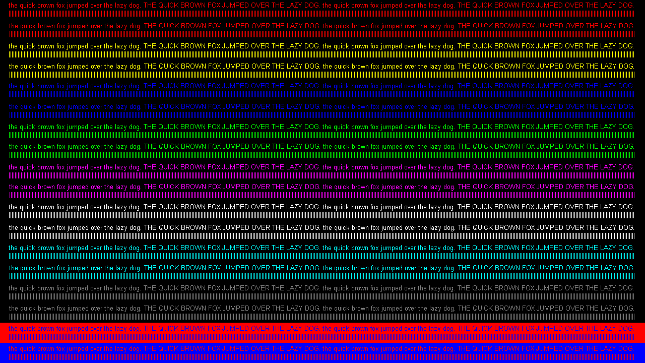
Color Correction
The Color Correction submenu is used for Morph 4K's HDR injection and Gamma adjustments.

| Setting | Details |
|---|---|
| HDR*** | Injects High Dynamic Range (HDR) metadata. HDR refers to the set of imaging technologies and techniques that allow the dynamic range of images or videos to be increased. Typically this refers to the difference between the darkest and the brightest parts of the image. The technology is used to render bright or dark scenes more accurately. HDR can also be used by the Morph to boost display brightness, typically to add in brightness that is often lost when using effects such as masks or scanlines. The following options are available: - Disabled: No HDR metadata injection is performed - Off (with CSC): No HDR metadata injection is performed but color correction controls are available for use within the standard definition image - HDR10: An open high-dynamic-range video (HDR) standard - HLG: Hybrid Log Gamma - A standard jointly developed by the BBC and NHK for high dynamic range (HDR) display Generally you should choose whichever mode works best on your display. Displaying SDR content within a HDR gamma curve will cause colors to be displayed incorrectly. The Morph has various controls to correct and compensate for this. |
| Color Profile | Use this to load a saved color correction profile from the microSD card. Click right on the remote and select it under /sdcard/presets/Color Correction (CSC). Then click OK to apply. |
| Input Gamma - Transfer Function - Factor - Gain - Lift - Bit Crush |
For adjusting the gamma curve as it is converted from the SDR gamma curve to the HDR gamma curve. Transfer functions available are Gamma, sRGB, SMPTE-240M, or Rec.709, and each has the option of adjusting the factor from 1.0 to 3.0. The input gamma's gain and lift can be adjusted along with the bit crush, set to off by default, by a scale from 1 to 7. Increasing the input Gamma may compensate for brightness lost when applying scanlines and/or masks, but care must be taken not to increase gamma too high and crush bright white parts of the image. Values can be incremented by 0.01 using the left or right navigation or by 0.10 (coarse) using the yellow or blue shortcut buttons on the remote. |
| Color Space Conversion - Overflow - Saturation |
For adjusting the color space conversion as it is converted from the SDR to HDR. Overflow can be set to attenuate or clip along with saturation of the color space. Saturation can be incremented by 0.01 using the left or right navigation or by 0.10 (coarse) using the yellow or blue shortcut buttons on the remote. |
| Output Gamma / PQ - Transfer Function - Factor - Nits - Dithering |
For adjusting the HDR output gamma curve or picture quality (PQ). Transfer function automatically changes depending on the HDR setting, and then the factor or nits can be adjusted. Dithering can be turned on or off. - HDR set to Off (with CSC) or HLG will set transfer function to Gamma. Factor can only be adjusted in increments of 0.1 using the left or right navigation or by 1.0 (coarse) using the yellow or blue shortcut buttons on the remote. - HDR set to HDR10 will set transfer function to SMPTE 2084 PQ. Nits can only be adjusted on HDR10 and is best used when a mask and/or scanlines are enabled. It can be incremented by 50 using the left or right navigation or by 500 (coarse) using the yellow or blue shortcut buttons on the remote. |
*** Using HDR modes requires a compatible television or monitor.
Output Resolution
Morph comes packaged with a set of 5 display resolutions. It is best to choose the highest resolution supported by your display. The exception to this is if you wish to utilize black frame insertion (BFI), in which case a 120hz display mode is best capable of handling the inserted black frames without affecting image quality. The current output resolution has an exclamation point (!) to the right. When choosing a new resolution, you must press the OK button once to confirm and then again to save the change. If you do not save the change within 20 seconds, Morph will revert to the previous screen resolution.
Additional resolutions can be added through the custom modelines option in the WebUI.

| Resolution | Details |
|---|---|
| 1080p | Displays a 1920x1080p 60Hz resolution. Supported by most modern TVs and monitors. |
| WQHD | Displays a 2560x1440p 60Hz resolution. Supported by most modern 1440p monitors, yet may be incompatible with some TVs. |
| 4K | Displays a 3840x2160p 60Hz resolution. Supported by native 4K TVs and monitors. |
| 1080p (120Hz) | Displays a 1920x1080p 120Hz resolution. Supported by most modern 1080p TVs and monitors with 120Hz support i.e. the screen is capable of refreshing 120 frames per second. |
| WQHD (120Hz) | Displays a 2560x1440p 120Hz resolution. Supported by most modern 1440p monitors with 120Hz support i.e. the screen is capable of refreshing 120 frames per second. May be incompatible with some TVs. |
Note: If you accidentally choose and confirm an incompatible resolution with your monitor or move Morph to a different display without first resetting the screen resolution, you can perform an emergency reset to 1080p 60hz. To do this, hold the right button on the front panel of the Morph for longer than 5 seconds. This will force the output resolution back to 1080p 60hz.

Advanced Video
Options in this menu affect the output of the Morph 4K's video.
| Setting | Details |
|---|---|
| Frame Lock | Engaging frame lock syncs the input refresh rate exactly with the output refresh rate. This usually results in the smoothest possible image movement/scrolling and the least amount of input lag. By default, this is set to Off (triple buffered). All options are as follows: - Off (triple buffered): Disables frame lock, which will uncouple the input and output frame rates. Turning off frame lock is essential for games which change between resolutions, such as 240p and 408i, as it will allow the Morph to re-sync the image as fast as possible. - Normal: Syncs the input refresh rate exactly with the output refresh rate, buffers a small number of lines so that picture parameters such as zoom can still be adjusted without causing an image re-sync - Minimal (lowest lag): Sets the minimum amount of buffering for the very lowest lag possible, yet you will lose the picture temporarily if you try to adjust the image zoom or aspect ratio |
| Triple Buffer | Changes the output frequency as long as Frame Lock is set to Off (triple buffered). By default this is set to Auto (50/60hz), yet can be set to Force 60Hz for NTSC input or Force 50Hz for PAL input. If you encounter a game title that has image drop outs between levels or loading screens, even when using Triple Buffer mode, try forcing the appropriate refresh rate rather than using the default setting. |
| BFI | Black frame insertion (BFI) causes every other frame to be black. This can improve motion clarity on some displays, at the expense of some image brightness. It is most useful when coupled with 120hz output resolution and HDR injection. |
| Color Space | Toggles the output color space. By default, this is set to auto, yet can be changed to limited for 16-235 levels of brightness or full for 0-255 levels of brightness. Full range RGB is very common for computer monitors and PCs while limited range RGB is usually used for video devices such as DVD players. Managing this difference in brightness levels across various devices is often challenging when the device sends incorrect EDID information to invalidate the selected color space. Auto is recommended for most setups, yet the setting may need to be changed in some cases. |
| AVI IF ITC/CN | IT content (ITC) and content type (CN) are two variables of the Sink Auxiliary Video Information (AVI) InfoFrame (IF). Basically, this field allows the disabling or selection of the content type field in the AVI IF. By default, it's set to Game. There are other options for media content (Cinema, Photo, Graphics) or it can be Disabled. Switching it to something other than Game is necessary if your TV may be processing the signal differently as per HDMI/ANSI CTA-861-I spec. |
| Inject VFR-EMP | Variable Frame Rate extended metadata packet (VFR-EMP) injects a flag or extra data packet on the HDMI signal to tell the display to expect a variable refresh rate image. Currently, this does nothing more than add the VFR/VRR flag to the signal, which has been shown to help some TVs when handling off-spec refresh rates. The available options are: - Disabled: Do not send VRR metadata packet at all. This is different from "off", since no VRR metadata is sent whatsoever to the display - Off: Sends a metadata packet to the display to explicitly disable VRR - Auto: Sends the appropriate VRR metadata packet based on the connected display EDID - Vesa: Send a metadata packet to the display to tell it to expect a VESA standard VRR signal - Freesync: Send a metadata packet to the display to tell it to expect a AMD Freesync VRR signal |
| RX DV1/FXD | Enables or disables detection and autoscaling of native DV1 metadata (~240p/480i) from MiSTer FPGA and PFX Digitals/GEMs. For some MiSTer cores, this may require the use of DV1 config files. |
| RX Input CS | For setting the input color space of the HDMI source. By default, this is set to Auto, yet in some cases may need to be changed. The setting appears greyed out when the input signal isn't HDMI. For example, if the input signal is DV1, then RX Input CS has no effect because DVI is always RGB full range by definition. The following options are available: Auto, Auto (no ITC), RGB AVI Limited2F, RGB Limited, RGB Full, YCbCr 601 Limited, YCbCr 709 Limited, xvYCC 601, xvYCC 709, YCbCr 601 Full, or YCbCr 709 Full. |
| RX 422 Interp. | For HDMI sources with 4:2:2 chroma subsampling, turn this option on. Otherwise, leave it off. |
| RX EDID | For setting the Extended Display Identification Data (EDID) detection of the HDMI input source. The default option is default.bin and for most sources, this is the best option to use. Yet in certain cases, another EDID may be required. Options are as follows: h-dac.bin (for Analogue consoles like Mega Sg, Super Nt, and Analogue Pocket Dock), a-dac-ntsc.bin, a-dac-pal.bin, or 2ch-pcm-only.bin. Advanced users can also use this option to select a custom EDID file. |
System
The System menu is comprised of submenus that allow you to keep Morph up-to-date with the latest firmware and configure various functional settings. The submenus are as follows:

WiFi
Morph includes an ESP32 chip with WiFi capability**** over a 2.4 GHz band (802.11 b/g/n). This allows you a few great features, such as the ability to easily check for firmware updates and update the firmware. It also expands access to Morph's Web Interface, offering a wireless remote control option and customizations.
In order to connect WiFi for the first time, you will need to run Start Setup Wizard to take you through the WiFi Setup Wizard. Once Morph has established a connection to your router, then the following fields are always present:
- SSID will show the router's 2.4 GHz SSID
- Ch/SigQ will show the router's 2.4 GHz channel value (1, 6, or 11 preferred), signal quality strength from Morph to the router (better if at least ~50%), and that the state is Connected
- Hostname will show Morph's default hostname morph4k.local for accessing the Web Interface
- IP will show Morph's assigned IP address from the router (either a 192.168.x.x address or different depending on router settings)
- MAC will show Morph's unique MAC address (can be used to identify it on the router)
- Web user and Web pass are hidden credentials to access the Web Interface and can be revealed using the red shortcut button on the remote
If the above fields look incorrect, then you may want to double-check the router's settings to ensure Morph can establish a stable connection with the 2.4 GHz SSID. You may even need to restart Morph or proceed through the WiFi Setup Wizard once more.
Additionally, you can open the Station Settings submenu to customize connectivity with three settings.

| Setting | Details |
|---|---|
| Auto Connect on Start | For Morph to connect over WiFi as soon as its powered on, this setting is best kept on. If you prefer to manually manage the WiFi connectivity, then turn this off. Then you can use the green shortcut button on the WiFi submenu to Disconnect WiFi. |
| Minimum RSSI required | For adjusting the Received Signal Strength Indicator (RSSI) of Morph's ESP32 antenna. This limits connectivity with routers over a wider distance as the detected signal quality strength will be considerably less. By default, this is set to 40% (-80dBm), yet this can be as low as 20% (-90dBm) and as high as 80% (-60dBm). In rare cases would you ever set this above 40% (-80dBm). To maximize compatibility with further routers, keep this at the lowest setting, 20% (-90dBm). |
| Disable credentials | For turning off the web user and web pass credentials required to access the Web Interface. By default, this is set to no. For ease of access to the WebUI, set this to yes. |
**** The ESP32 is configured to support WiFi only. There is no support for Bluetooth.
Firmware
The Firmware submenu is used to manage firmware updates either downloaded directly to Morph over a WiFi connection or accessible from your microSD card. It is comprised of a few operations:
| Operation | Details |
|---|---|
| Release Notes | Allows you to view release notes on the selected update channel starting from the most recent firmware version to the earliest and contains list details for new features, fixes, and/or general improvements. If you prefer to view these release notes on a PC or mobile device, they can also be accessed from https://firmware.pixelfx.co/. |
| Update Channel | The Morph has several update channels which may contain the same or different firmware versions. By default, the Stable channel is selected. Each update channels is described below. - Stable: This channel contains firmware that has been thoroughly tested and proven to be suitable for general use - Testing: This channel has firmware that may contain new features still in development with minor bugs or errors - Unstable: This channel has firmware that may contain new features heavily in development and not yet thoroughly tested so bugs or errors can appear |
| Check for Update | Allows you to run a firmware version check against the PixelFX server on the selected update channel to compare the staged and installed firmware versions. When these values are equal, then you will see the message "Firmware is up-to-date." When these values are not equal, then you can click OK to check release notes for the version differences and either click back to exit or click OK to initiate a firmware update. For the full list of steps to implement the firmware update, check out Updating via WiFi. |
| Update Firmware***** | Allows you to stage and install the newest firmware update available from the PixelFX server based upon the selected update channel. For the full list of steps to implement the firmware update, check out Updating via WiFi. |
| Update Firmware from SD Card | Allows you to install firmware from the microSD card. For the full list of steps to implement the firmware update with a microSD card along with alternative methods, check out Updating via SD Card. |
| Select Alternative Firmware | Allows the user to change the FPGA firmware on the fly. A standard firmware update installs new firmware for the ESP32 and FPGA through a full installation process. This option allows you to change just the firmware FPGA file in a few seconds. While no alternative firmware are currently available, in the future this functionality will allow the user to keep alternative FPGA firmware on the microSD card and change between them without needing to do a full firmware installation. |
***** As of the 3.9.x firmware, a microSD is always required to run Update Firmware.

OSD
The OSD submenu contains two sections that affect Morph's on-screen display (OSD) text, position, and screen visibility and are split across two sections: Settings and Position.
Settings
| Setting | Details |
|---|---|
| Font | Allows you to change the font, or typeface, used across all menus and submenus. By default, this is set to iso.font. Other font choices are as follows: default.font, display.font, fancy.font, font2.font, iso88591.font, and tremolo.font. |
| Endless menu | Allows menu and submenu cursors to move from top to bottom of the screen continuously through remote navigation input without impediment. By default, this is set to off. |
| Endless FB | Allows menus and submenus file browsers (FB) to wrap around long file name text rather than cutoff the file name due to length. By default, this is set to off. |
| CEC | Allows Morph to be detected and controlled via by TV or monitor remotes and other devices that support Consumer Electronics Control (CEC). By default, CEC is enabled and is a useful way to control Morph with another remote out of convenience. In some cases, this may cause interference with certain TV remotes and need to be disabled. |
| Version Check | Allows Morph to check for check for a new firmware update automatically and display a notification. WiFi must be setup and connected for this to work. By default, this is set to check once every power cycle, yet can be turned off or set to check always. |
| Notifications - Animation - Timeout |
Allows you to customize the animation speed and timeout length of any firmware or system notifications. Speed and timeout can be incremented by 1 using the left or right navigation or by 10 (coarse) using the yellow or blue shortcut buttons on the remote. Any changes can be saved and tested using the red shortcut button on the remote. |
| Screensaver | Allows you to display a screensaver after a set limit of inactivity. Similar to a DVD player logo screensaver, Morph's screensaver will display a Morph logo that will bounce along the screen. By default, this is set to off and can be changed to 10sec without signal, 1mins without signal, 2mins without signal, 3mins without signal, 4mins without signal, or 5mins without signal. |
Position
| Setting | Details |
|---|---|
| Menu H-Align | Allows you to shift the horizontal positioning of the menu via Left, Center, or Right. By default, this is set to Center. |
| Menu V-Align | Allows you to shift the vertical positioning of the menu via Top, Middle, or Bottom. By default, this is set to Middle. |
| Menu Margin | Allows you to shift the alignment towards the center when Menu H-Align and Menu V-Align settings place the menu along any screen border or corner. By default, this is 0, yet it is useful when the OSD appears off center on certain screens. |
| Menu Padding | Allows you to surround the menu with a layer of additional pixel padding the more you increase this setting. By default, this is set to 8. |
Morph Settings

The Morph Settings submenu contains settings that affect Morph's general operation and debugging.
| Setting | Details |
|---|---|
| LED - Red + Green + Blue |
Allows you to customize the color of the physical LED visible from the front panel using a hexadecimal color value scale (0-255 / 0x00-0xff). By default, Red is set to 000 / 0x00, Green is set to 255 / 0xff, and Blue is set to 255 / 0xff. To turn off the LED completely, set all values to 000 / 0x00. Values can be incremented by 1 using the left or right navigation or by 10 (coarse) using the yellow or blue shortcut buttons on the remote. If you need help deciding on a custom color, try a color picker. |
| Menu - Red + Green + Blue |
Allows you to customize the color of the Morph banner at the top of every menu and submenu using a hexadecimal color value. By default, Red is set to 000 / 0x00, Green is set to 255 / 0xff, and Blue is set to 255 / 0xff. Setting all values to 000 / 0x00 or 255 / 0xff will turn the Morph banner white. Values can be incremented by 1 using the left or right navigation or by 10 (coarse) using the yellow or blue shortcut buttons on the remote. If you need help deciding on a custom color, try a color picker. |
| Preset auto-load | Allows you to automatically load preset files stored under the /sdcard/presets/Auto directory via the microSD card when turned on. More details can be found under Presets. By default, this is set to off. |
| Overscan marker | Sets a temporary overscan region behind a visible display chosen within the Input menu or while using Border Detect. By default, this is set to on. |
| Write debug log****** | Allows you to write a debug log file called debug.txt to the root directory of the microSD card. This is useful in the event you encounter a problem or issue using your Morph and need to share your debug log with PixelFX. By default, this is set to off and can be changed to yes (overwrite) to write over the file on each power cycle or yes (keep) to continuously record lines without losing debug history. The debug log can easily be accessed from the Web Interface at http://morph4k.local/sdcard/debug.txt. Currently TX, RX and Clock events are recorded as well as other notable events. In order to locate events in their context, you can use the Number 5 button on the Morph remote to create a user mark in the log file (such as when a sync drop occurs) to assist in inspecting the debug log for unusual behavior in proximity to the recorded user marks.******** |
| Signal modifier | Allows you to change Morph's HDMI transmitter charge pump current. By default, this is set to off. Turning this on is recommended when using a very long HDMI cable or when advised during troubleshooting by PixelFX support. First check for the existing value via the Web Interface URL http://morph4k.local/signal_modifier/VALUE, then replace VALUE with a different option i.e. 0, 1, 2, 3. |
| Fan setting | Allows you to control the speed of a fan that is installed inside the Morph case. By default, this is set to full, yet the value can be decreased on a scale starting from 255 down to 0. Decreasing the value is useful to reduce the speed of a 5V fan to help with noise. However, this only works as long as the 5V fan supports reduced speeds. When not supported, especially with 12V fans, reducing the value will turn off the fan. It can be incremented by 1 using the left or right navigation or by 10 (coarse) using the yellow or blue shortcut buttons on the remote. |
****** Timestamps in the debug log file are in GMT as long as Morph is connected to WiFi (otherwise timestamps will be based on the Unix epoch (starting "Thu Jan 1 00:00:00 1970"). This will also happen for debug log entries before WiFi has been connected the first time after a power cycle. The debug logger also writes a "---- mark ----" to the log file every minute without other log activity. It's normal to see some SCDC errors during startup or resolution changes, especially with frame lock enabled.
******** If you're using an alternative IR remote that you programmed through the Web Interface, then make sure to add this to the custom ir.ini file for the included Morph remote: * command_num_5 = 0xf609.
SD Card Info
The SD Card Info submenu contains information on the currently inserted microSD card, including file system type, speed and free space.
| Field | Details |
|---|---|
| Name | Displays the name appended to the microSD card. If the name is unknown, then it will display as SM <size> (Example: SM32G). |
| Type | Displays the microSD card type. Modern microSD cards will appear as SDHC/SDXC. |
| Speed | Displays the speed detected by the microSD card. Currently, ESP32 displays this as 20.00 MHz (limit: 20.00 MHz). |
| FS-Type | Displays the formatted file system type of the microSD either as FAT32 or EXFAT. |
| Size | Displays the total capacity of the microSD card with a 3% reduction for system reserve that occurs during formatting. |
| Free | Displays the total available capacity of the microSD card for any new file system writes. |
Game ID
The Game ID submenu contains settings related to Game ID. Game ID allows supported consoles and devices (such as PixelFX's xDigitals and Retro GEMs) to transmit which game or software title you are currently playing over to Morph. Additional PixelFX links pertaining to advanced use of Game ID:
| Setting | Details |
|---|---|
| Resolve id to name online | Allows Morph to match the detected Game ID value against the exact title from an online database on consoles and devices that support Game ID. By default, this is set to off. Turn this on if you want to see the game titles appear at the bottom of the Morph menu. Game ID is also useful when auto loading presets created for select games. |
For more instructions on setting up your Game ID compatible device to work with Morph, see Game ID's Morph 4K section].
EDID
Dumps the EDID information of the device connected to the Morph 4K's HDMI input, typically for debugging purposes, and allows it to be downloaded through the web interface. Extended Display Identification Data (EDID) is a metadata format for display devices to describe their capabilities to a video source.
Follow the on-screen instructions to download the generated EDID file.
Debug / Self Test
The Debug / Self Test submenu displays various debugging/self test information about the Morph 4K, including temperatures and current processing/input lag. Click OK to reset the self test and check all fields on the top and bottom sections. Click the yellow shortcut button on the remote to view the CEC section.
Top Debug / Self Test Section
This section performs a health check of the following fields.

| Field | Details |
|---|---|
| Clock Source | Detection for the FPGA's clock source. This will either display CLKIN (clock input) when Frame Lock is set to minimal (lowest lag) and normal, or display XTAL (crystal oscillator) when Frame Lock is off (triple buffered). |
| Clock Input | Detection for the FPGA's clock input signal. When this is healthy, you will see ❤️. |
| PLL_A Lock PLL_B Lock HDMI PLL Lock |
Detections for the FPGA's phase lock loop (PLL) signals, which are essential for clock management. When these are healthy, you will see ❤️. |
| Monitor Sense | Detection for the FPGA's monitor sense signal. When this is healthy, you will see ❤️. |
| Hotplug Detect | Detection for the FPGA's hotplug detect (HPD) signal for the incoming 5V power. When this is healthy, you will see ❤️. |
Bottom Debug / Self Test Section
This section verifies status of the following fields.
| Field | Details |
|---|---|
| Lag | Displays the lag response in milliseconds (ms). This is useful for checking lag when Frame Lock is set to minimal (lowest lag) or normal. In minimal (lowest lag), lag will dial-in around 1ms. In normal, lag will dial-in around 6ms. However, if Frame Lock is off (triple buffered), then the lag will consistently fluctuate from around 16ms down to 0ms and this is standard behavior. |
| Input CS | Displays the input color space (CS), which is typically 24bit. This is useful for testing color input from games that use 24-bits (8-bits each for RGB). |
| Core Temp | Displays the FPGA's core temperature in both Celsius (°C) and Fahrenheit (°F). This is useful to monitor temperature levels of the FPGA during gameplay. Standard operation is between ~55-65°C and this can vary for Morph based on environment and airflow, etc. When Morph's HDMI input is fed a 1080p signal, then the temperature will rise to ~70°C. This is still perfectly healthy since the FPGA's operating junction temperature is 125°C. |
| M-Trig. | Displays matrix trigonometry. Currently only shows a 0. |
| IR Address | Displays the infrared (IR) address of the remote control in the form of a hexadecimal code. This value will remain the same when pointing the remote at Morph to test, whether that's the remote that comes with Morph (0xfe01) or for a custom remote. |
| Command | Displays the command referenced by the IR remote control for each button in the form of a hexadecimal code. This value will change when pointing the remote at Morph to test different buttons. |
CEC Section
| Field | Details |
|---|---|
| Enabled | Displays true or false depending on whether the CEC setting under the OSD submenu is set to on or off. |
| Physical address | Displays the physical address for Morph and appears as 1.0.0.0. |
| Logical address | Displays the logical address for Morph and may appear differently depending on the HDMI input/output connections. Common values are 4 (Playback Device 1) or 8 (Playback Device 2). |
Snake

The Snake submenu is PixelFX's version of the popular classic video game, Snake. This is useful when you want to easily play a game in the OSD without powering on a separate device or console.
| Controls | Details |
|---|---|
| Navigation | Press up, down, left, and right on the included remote, custom remote, WebUI's OSD remote, or CEC remote to start the game. Then press each button to move the head around to collect each ❤️ to expand your snake. |
| Speed | Navigating left or right moves incrementally. Navigating up or down moves at twice the incremental speed. |
| Cancel/Exit | Use the back button when finished to cancel/exit the game. |
Factory Reset
The Factory Reset submenu is meant for forcing a reset on settings or updates. This is useful if a firmware update or configuration change causes an operational error, yet will revert a plethora of settings back to defaults so choose the option that best applies.
| Option | Details |
|---|---|
| Reset WiFi Settings | Choose this option to remove the current WiFi configuration and station settings. For example, say you change your home router/access point. Morph can only store the credentials for one access point at a time. Proceeding through WiFi Setup Wizard can enable a connection to a new access point, but in rare cases, this may have trouble and can be remedied resetting WiFi settings. |
| Reset all Settings to Default | Choose this option to reset settings across all menu and submenus to their default values. However, any files stored on the microSD card remain (presets, debug log, firmware, etc). |
| Reset all Settings keep WiFi | Choose this option to reset settings across all menu and submenus to their default values, with the exception of the WiFi configuration and station settings. Also, any files stored on the microSD card remain (presets, debug log, firmware, etc). |
| Force Firmware Update | Choose this option to reset the firmware updater so a new version is found the next time it is executed, even if the checksum of the firmware on the server matches the firmware that is currently installed. Generally, you would only use this option when advised during troubleshooting by PixelFX support. |
| Force Preset Install/Update | Choose this option to reset the preset updater so a new version is found the next time it is executed, even if the version of the preset archive matches the version currently installed. Generally, you would only use this option when advised during troubleshooting by PixelFX support. |
Info
The Info submenu displays important information pertaining to Morph 4K's hardware and software.
| Field | Details |
|---|---|
| Device-Id | Displays the full device ID unique to each Morph. This is useful for downloading firmware updates directly to the microSD card. |
| Hardware-Id | Displays the full hardware ID unique to Morph's printed circuit board (PCB) build based on manufacturing date and revision. |
| Firmware-Version | Displays the current version of the FX Framework firmware installed on Morph. |
| Bootloader/Rescue-Version | Displays the current version of the bootloader and rescue system installed on Morph. |
Restart
The Restart menu is to simply restart Morph 4K or put it into standby mode.
| Operation | Details |
|---|---|
| Enter Standby Mode | Engages a standby mode, a low power/sleep mode for Morph. This is where the OSD and source on the screen will disappear on the TV or monitor. This will also turn the LED on the front panel white. If an HDMI input source is still active, Morph's rear LED will remain orange. The WebUI is still available, yet features are limited. The only way to come out of standby mode is to either press the red power button on the remote or power cycle Morph with the physical switch on the front panel. |
| Restart Morph | Engages an instantaneous power cycle to restart Morph where the OSD and source on the screen will temporarily disappear on the TV or monitor, and then within a few seconds, the source will reappear and the OSD can be reopened. If no source is active, the No Signal! display will appear and the OSD can be reopened. |
RX Input Analyzer
Displays various diagnostic information for the current input, these pages are informational only, there are no settings to change here. The information you can view is as follows:-
- RX Status
- RX Input Timings
- RX Input Audio
- RX AVI InfoFrame
- RX SPD InfoFrame
- RX VS InfoFrame
TX Info
Displays various diagnostic information for the current output, these pages are informational only, there are no settings to change here. The information you can view is as follows:-
- TX Output
- TX SCDC Status
WiFi Setup Wizard
Note: WiFi Setup Wizard saves settings on the microSD card. Be sure to use a compatible microSD card and format before proceeding. An incompatible microSD may cause Morph OSD to freeze during WiFi Setup Wizard.

To setup WiFi on Morph for the first time, you will need to perform the following steps:
- With Morph powered on via physical switch, use the remote to open the main menu by pressing either the Menu button (shaped like 🏠) or OK button.
- Navigate to System > WiFi > Start Setup Wizard and then press OK on the remote to begin.
- A QR code will appear on the menu. Use your phone's camera to scan the QR code, click on the popup link underneath the scanned QR code, and then your phone will establish a WiFi connection to Morph's wireless access point.
- If you have trouble with the QR code, then you will need to manually change your phone's (or PC's) WiFi settings. Select MORPH 4K from your WiFi's SSID list and enter the password MORPH 4K (all capital letters).
- If DHCP is disabled on you phone or PC and you're using a static IP address, be sure to re-enable DHCP in order to connect to the MORPH 4K SSID.
- Once your device is connected to Morph's access point, a second popup link will appear underneath the scanned QR code. Click on the link and it will automatically open the WiFi Setup Wizard in a browser window.
- If this fails to open automatically, then manually open a browser window and type into the address bar http://192.168.4.1/wiz.
- For Select WiFi Network, a list of nearby SSIDs will appear. Choose your router's SSID and then click Next.
- For Enter WiFi Password, type in the exact password for your router's SSID. Click on the eye icon to the right of the field in order to reveal the password, confirm it looks correct or make any revisions, and then click Next.
- For Set WebUI Credentials, enter a username and password you want to use in order to access Morph's Web Interface. If you do not make changes to the fields, they will both default to morph4k. Click Next.
- For Save & Apply, confirm all of your settings look correct. If you need to make any changes, click the Back button. If everything looks good, then click Finish to save your settings and restart Morph.
- Confirm Morph is now connected to your router's SSID by opening Morph's main menu again and navigating back to the WiFi submenu.
Router Compatibility
If Morph fails to connect to your router's SSID, then you may need to adjust some settings on the router to ensure a 2.4 GHz band (802.11 b/g/n) is enabled. It's very possible the router may be using default settings that can impair the connection to Morph's WiFi antenna.
In order to make these changes, you will need access to the router's administration portal. If you own the router, then login to the administration portal with the username and password you defined during initial setup (or check the router's instruction manual for the default username and password).
Note: If the router is managed by your ISP, then reach out to them for assistance with changing these settings on the router's administrative portal.
- In the router's wireless settings, verify that Smart Connect is disabled. Smart Connect tends to be configured automatically when using a router's quick setup method. While it combines the router's 2.4 GHz and 5 GHz bands into a single SSID, this means the router automatically reserves the 2.4 GHz and 5 GHz on a device-by-device basis which can severely impact device compatibility if incorrectly assigned by the router.
- If the router's 2.4 GHz and 5 GHz bands are separated, there will be two SSIDs. Check the 2.4 GHz SSID's settings and make sure the security option is set to WPA2/WPA3 Personal or similar. Morph's WiFI antenna supports WPA2 Personal, and including WPA3 will greatly increase your router's compatibility to accept newer devices.
- While reviewing the 2.4 GHz SSID's settings, verify:
- The channel is set to either 1, 6, or 11. These are non-overlapping channels and are less susceptible to interference from nearby routers or other wireless network devices.
- The channel width is set to 20 MHz. If this is set above 20 MHz, there's a higher likelihood of interruption due to sharing the same network connection with other devices.
- If the above settings look correct, then as a last resort restart the router before going through the WiFi Setup Wizard again
- Unplug the power cable/turn off the router
- Wait 60 seconds and then plug the power cable back in/turn on the router
- Wait at least 5 minutes for the router to re-establish internet connectivity to all devices
If you prefer to connect Morph to your phone's mobile hotspot (i.e. a wireless access point that uses cellular data), then make sure it is enabled for 2.4 GHz before proceeding with the WiFi Setup Wizard.
- For iPhone
- Go to Settings > Personal Hotspot
- Verify Maximize Compatibility is turned on
- For Android (example Samsung Galaxy S24)
- Open Settings > Connections > Mobile Hotspot & Tethering
- Click on Mobile Hotspot
- Verify Band is set to 2.4 GHz